Figure: Thecus chassis for five disk bays, open
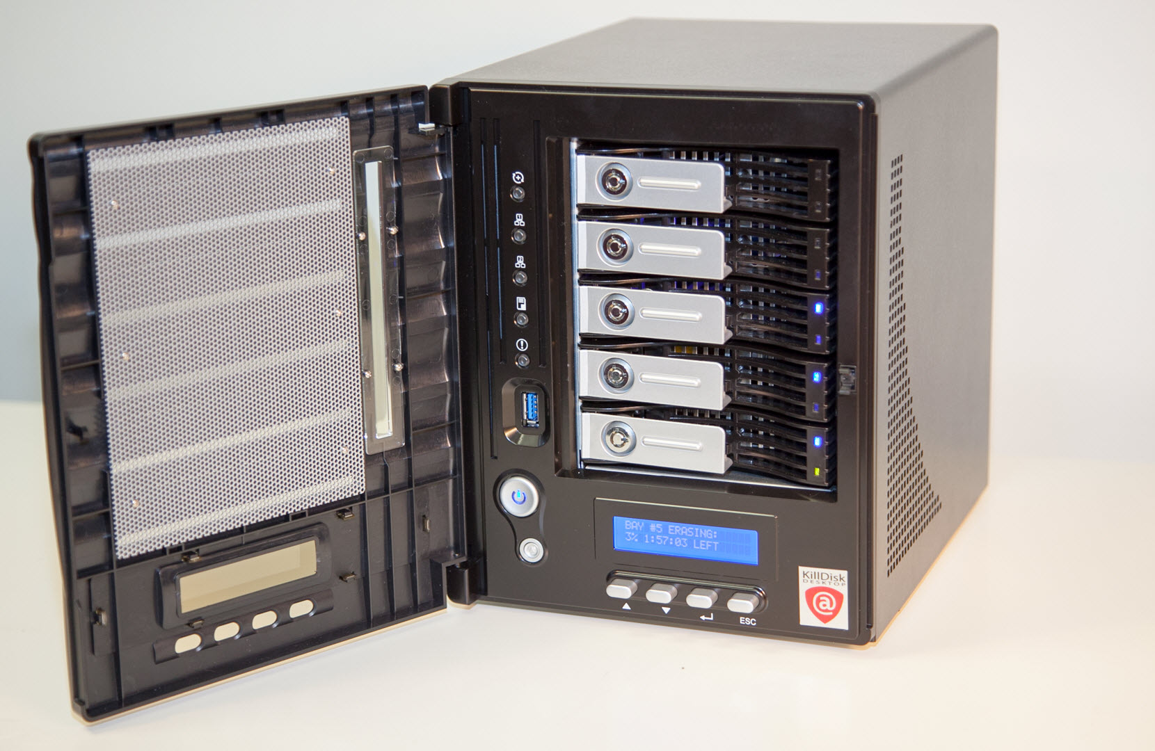
Thecus chassis components (front)
- 5 x HDD bays
- The chassis has 5 disk slots with removable bays for the system to perform actions on up to 5 hard drives at a time. The bays support 2.5" and 3.5" SATA disks for use with standard HDD's and SSD's. They are also physically lockable using the keys included in the system.
- Disk status LEDs
- Each disk bay contains two status LEDs to monitor the bay status and activity.
- USB 3.0 port
- Connect USB devices to KillDisk Desktop with high-speed USB 3.0 support.
- 5 x LED light indicators
- 5 LED indicators are used to give feedback to the user on KillDisk oeprations
- Power button
- Powers on the Thecus hardware unit.
- Reset button
- Resets the hardware unit.
- LCD display
- Describes current process, allows user to navigate and access KillDisk menus, initiate processes and see progress.
- Navigation buttons
- Buttons allow user to navigate menus on the LCD display, built into the hardware.
Figure: Reverse side of Thecus chassis

Thecus chassis components (back)
- Power switch
- Master power switch for the unit.
- Power cable connector
- Connector for a NEMA 5-15-P, 3 pronged power cable.
- Audio and microphone connectors
- Standard connectors. Not necessary for any KillDisk operations.
- 1 x eSATA port
- Standard, high performance eSATA port for connecting drives to the KillDisk Desktop hardware.
- 4 x USB 2.0 ports
- Standard USB 2.0 ports. May be used for connecting storage devices or peripherals (i.e. mouse and keyboard) to the system.
- 1x HDMI port
- Standard HDMI port. May be used to connect an external monitor to the KillDisk Desktop system.
- 1 x VGA port
- Standard VGA port. May be used to connect an external monitor to the KillDisk Desktop system.
- 2 x Ethernet port
- Ethernet ports for networking with the system.
Thecus Lights and Indicators
The system has two main areas with lights and indicators: the chassis and the individual hard drive bays. This section will outline what these indicators represent.
Figure: Thecus LED indicators

The chassis has 5 LED indicators along the left side of the hardware unit, each indicating toward different states of the system.
| Item | Description |
|---|---|
| 1 - Activity Indicator | Flashes during any KillDisk active process, such as Erase, Examine, loading, etc. |
| 2 - LAN 1 Indicator | Lights up when the LAN 1 port is used. |
| 3 - LAN 2 Indicator | Lights up when the LAN 2 port is used. |
| 4 - Not used | - |
| 5 - Critical Error Indicator | Lights up in red when a critical error occurs in the system. |
Disk bays have their own LEDs that are utilized to give the user information on the current status of the individual bay (or disk using the bay).
| Item | Description |
|---|---|
| 6 - Active Disk Indicator | Green, solid when disk bay is being used. |
| 7 - Disk Status Indicator | Green, flashing - Read/write activity |
| Red, solid - erase finished | |
| Red, flashing - read/write error |
Figure: Thecus chassis for five disk bays, disk swapping
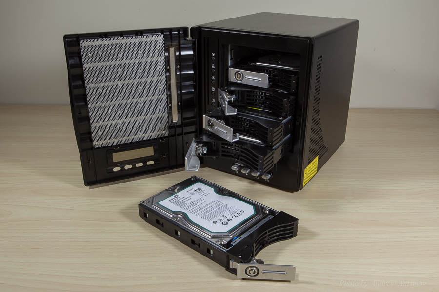
Figure: Thecus chassis for five disk bays, front panel controls and display
