Disk Bay Layout
The purpose of Disk Bay Layout is to match Active@ KillDisk's graphical disks' representation to your actual hardware configuration making it easy to manage disks for erasure, examination, cloning and more. To illustrate this let's look at the example, using the hardware below:
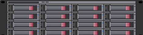
In the example above we have a generic disk array consisting of 16 disks arranged in a 4x4 grid. The machine using these disks would see the disks similarly to Active@ KillDisk's Local Devices view.
There are two types of Disk Bay layouts:
- Free Grid Layout
- This feature allows you to position the Disk Bay widget at any location, change the Bay widget size, and adjust its
alignment (vertical or horizontal) individually for each Bay. This enables you to create an accurate layout that mimics the actual
physical disk Bay slots on your hardware chassis.
Figure 2: Free Grid Layout 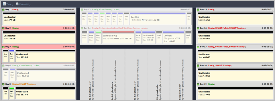
- Table Layout
- Is similar to Disk Bay Layout from previous versions. However, now user can re-size or select Disk Bay widgets by
using row and column headers.
Figure 3: Table Grid Layout 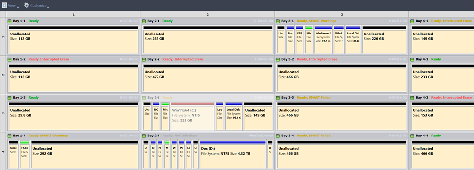
Now imagine inserting a HDD into the bottom-leftmost Bay of the disk array. Even finding the device in a list of 15 other disks would be tedious and not very intuitive. This is when creating a Disk Bay Layout is extremely useful. By creating a 4x4 Disk Bay Layout we can map the physical ports to their corresponding Bay in Active@ KillDisk and visually see our disk array like this:
Assuming that the Bays were mapped correctly finding the correct disk to manipulate with is now much easier in the Disk Bays view than it would have been Local Devices. You can now select the bottom-leftmost disk in the Disk Bays view and perform any necessary actions on it.
Disk Bay list Tree
In some cases it may be convenient way to work with Disk Bays presented in Disk Bay layout as tree-organized list with grouping by columns (rows).